flow control valve.....

the WaTeRhAwK

fryin' up a/m electrics..
Location
okc
Since it looks like you are currently controlling the amount of water flow into the head pipe I was saying to leave it full flow into the head pipe and control when you want to bypass a good portion of the water to prevent over loading the chamber with too much water at higher rpms. This will allow a bigger orifice at the spray point in the headpipe. By altering the orifce diameter and relief pressure point you should be able to dial it in.

I'm already doing this and it sux, because I have to reach under the hood and open it up when I want it to jump out of the water, then when I want the speed to come up I have to close it down some to get the rpms up while keeping the coupler from melting off.
as far as "dialing it in" goes, there really isn't any. set at an even rate it takes away from both areas of the powerband.
 
I thought you were adjusting the water going into the headpipe I don't mean into exhaust stream. If you have a fixed outlet diameter and are currently adjusting via an orifice the amount of water going in the water jacket you are also adjusting how much goes into the exhaust stream, by adjusting the point of bleed off you can somewhat control the water pressure in the water jacket of the headpipe and have better control of the water volume by using a larger diameter orifice to feed larger amounts of water at lower rpms and when the rpms and the water pressure rises the flow valve will open so as to not over saturate the chamber at higher speeds.
I think the only way an ecwi would work is by supplementing additional water on top of whatever you decide to have fixed. The only gain would be by the sonic wave being changed by the amount of water and not by the changing of the tuned length because the headpipe you are using is very short.
 

the WaTeRhAwK

fryin' up a/m electrics..
Location
okc
by adjusting the point of bleed off you can somewhat control the water pressure in the water jacket of the headpipe and have better control of the water volume by using a larger diameter orifice to feed larger amounts of water at lower rpms and when the rpms and the water pressure rises the flow valve will open so as to not over saturate the chamber at higher speeds.


that's what I thought you meant to begin with.
how exactly would you modify it to allow this to occur? putting a larger diameter tube welded into the headpipe to dump into the chamber?

on the newer setup, the cast aluminum kerker headpipe has a very small pinhole spraying or drizzling water down into the chamber, to get it to perform on the bottom like the old chamber setup, I would have to drill that hole larger so it would dump more water.

picture.php


although, as it is, on the newer setup pipe with the stinger fitting, it doesn't bleed off enough from the headpipe when the fcv opens, with the limiting valve set at full flow. there's just too much force of water coming from the pump.
motorheads has the right idea with the device he was talking about making, but I'll have to experiment with making one quite a bit and get it adjusted to fix the problem, unless I can figure out an alternative route.
 
Yes you would have to add a second outlet on the headpipe and have that out pop off with the flow valve right after the pipe hits and that would help control the amount of water getting into the exhaust stream. If it is the old all stailess headpipe you can drill and weld another outlet on the outer shell.
 

the WaTeRhAwK

fryin' up a/m electrics..
Location
okc
So what's wrong with drilling a hole in the center of the disc for minimum flow ?
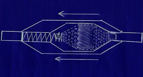

yeah, I figured that's what you meant when you said to drill "holes" in the disc, depending on the inside design, I don't know if it would need a center hole drilled or not. if the seat around the spring that the disc goes against is flat or has a shelf that would block the holes and close off the flow, then yes, it would need a center hole drilled to set the minimum flow.

I was thinking about making the inside of the valve a conical shape, with a cone-shaped insert with the holes drilled in it, set on a spring, with the spring tension adjustable like the fcv setup. most of the water will flow around the cone until the pressure shuts it off, then the only water flow getting to the headpipe will be through the holes in the cone insert.
 

the WaTeRhAwK

fryin' up a/m electrics..
Location
okc
motorheads, I've been drafting a few different ideas of your design here. I'm working on getting my damned scanner to work so I can show you what I have so far, but this friggin scanner is a pita.
 

Motorheads5

Livin the generation gap
Location
ketchikan alaska
I am laughing right now no :):):):) either because I like your approach on this dude. I think you are on track here ok, but maybe I need to try and do a drawing of what I have in mind I am thinking more along the lines of a bendix air compressor type of a check valve in other word's imagine a quarter with a lot of holes drilled in the outside perimiter that will flow fine at low flow and low pressure because of the spring tension and after the pressure or volume overwhelm's the holes in the disc it slam's shut after that the only water you will get comes from the size of hole you drill in the center of the disc. HOLY CRAP DUDE I don't type my thought's very well lmao I hope yopu can read it lol
 

the WaTeRhAwK

fryin' up a/m electrics..
Location
okc
yes, I was picturing the "quarter" type if insert when I read your initial post. the reason I drew the diamond type of insert with the holes (also a larger diameter hole through the center) is because I got to thinking about it a little more, and I figured at the idle part of the rpms, it would be dumping into the chamber at full flow, which pretty much defeats the purpose of running the jetworks fcv between the head and the stinger fitting, because it would not be at a minimal flow setting, and wouldn't be minimized unless the water pressure was up to compress the spring.
with it set up with the conical area on both ends of the insert or "slug", fully retracted, it sits against the conical inlet area of the housing at a "minimized" flow setting. as the rpms are increased and the water pressure from the pump moves the slug forward it frees up the outer holes in the slug to fully flow water until the over bearing pressure causes the spring to compress and minimize the flow at the other end. with the proper spring tension, this will allow the water to be minimized at low rpms, then as the rpms increase towards midrange, it will dump water into the chamber for a second and then shut down to a minimized setting as the spring in compressed and the rpms go in to peak range.

I need a lathe and some billet aluminum rod to make this thing.
 

the WaTeRhAwK

fryin' up a/m electrics..
Location
okc
if I end up being able to mass produce these things, and people want them, you're gonna end up makin some money off of this thing, this was your idea..lol
 

the WaTeRhAwK

fryin' up a/m electrics..
Location
okc
I think you are on track here ok, but maybe I need to try and do a drawing of what I have in mind I am thinking more along the lines of a bendix air compressor type of a check valve in other word's imagine a quarter with a lot of holes drilled in the outside perimiter that will flow fine at low flow and low pressure because of the spring tension and after the pressure or volume overwhelm's the holes in the disc it slam's shut after that the only water you will get comes from the size of hole you drill in the center of the disc.


have you drafted anything yet? just checking. : ) I'd like to see it if you have.
 
Top Bottom