- Location
- Nova Scotia, Canada
I just had my ebox JSS'ed and also sent my cdi to a dood here on the x to make the rev limiter adjustable.
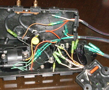
I have a wiring diagram here, but things don't look the same in the book as they do in my ebox. So I'm not sure if maybe John changed things around in there (haven't been able to get in touch with him for a couple days) so I'm hoping there is someone here who can tell me if the following sounds reasonable:
CDI - 7 loose wires
------------------
(1) Black goes to ground post AND to black on coil
(2) Black goes to a black wire that then goes to a ground post and then to the black wire leading to stator?? Maybe this female black is no longer used, since the black leading to the stator is grounded to a post.
(3) Brown/White goes to Brown/White that leads to stator
(4) White/Red goes to White/Red that leads to stator (my JSS'ed ebox only had "White" going to stator - I assume that's the one)
(5) Orange goes to Orange on coil
(6) Pink - leave disconnected (used to go to thermo switch) (was the 3rd grommet on top previously for a thermo switch wire?)
(7) White goes to White wire on stop switch
")
