Super Jet 1996 Round Nose SuperJet Project

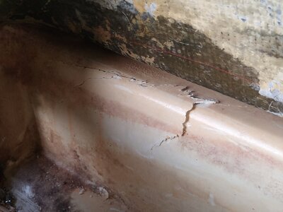
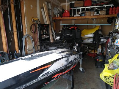
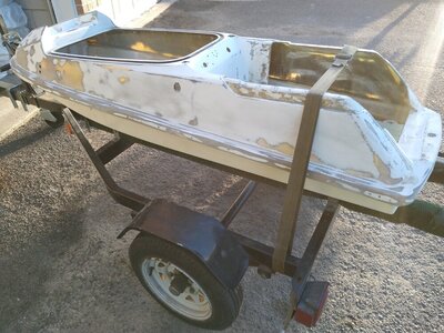
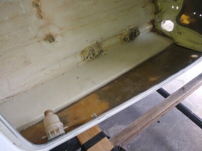
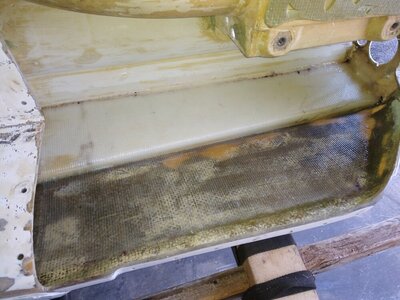
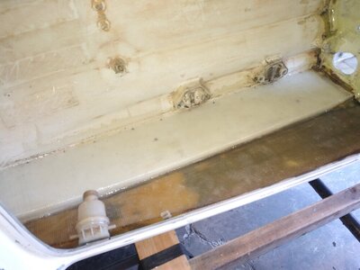
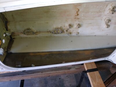
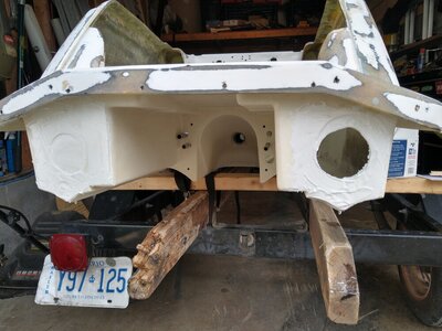
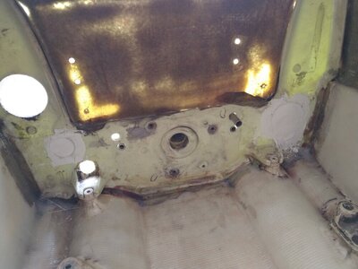
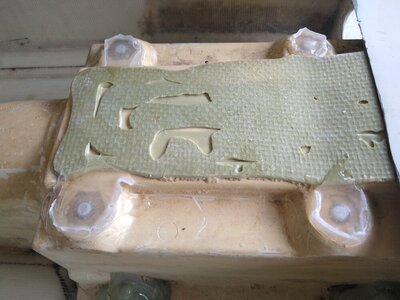
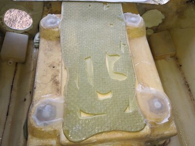
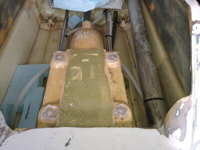
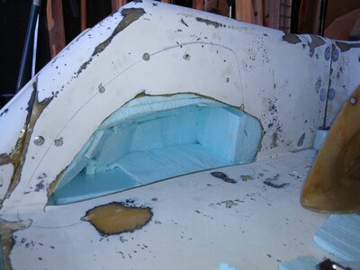
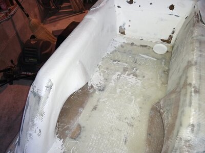
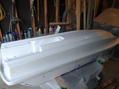
I'm resurrecting my old thread. I can't believe I have had this ski for 8 years now :oops: But, I am back into the tray hauling it all apart again. My reason is that the bottom deck of my tray section has broken open leaving a rather substantial breach on both sides. My thoughts are this happened from the removed original expanding foam leaving the tray area lacking internal structure. The pool noodles will compress a lot and couldn't be jammed in there tight enough to give adequate structure so I will be removing and discarding those. The idea was given to me by Quinc to use rigid foam that can be bought at Home Depot. I went a step further and researched the foam variants because it came to memory that there has been a lot of question on here about what is a good alternative to the expanding foam. I too agree to that, I didn't like the mess of the original stuff when I cleaned it out, and I didn't want to do it again should there be a reason to get back inside the tray section. Having researched foam for a good portion of the last 4 or 5 days, I have found that the most applicable foam for my needs is a high density ground support foam with a compressive strength of 100 psi.

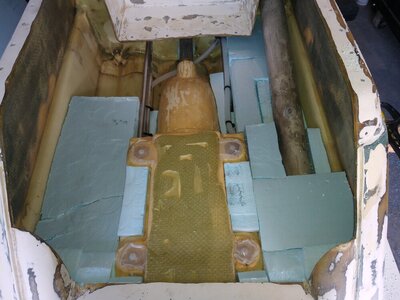
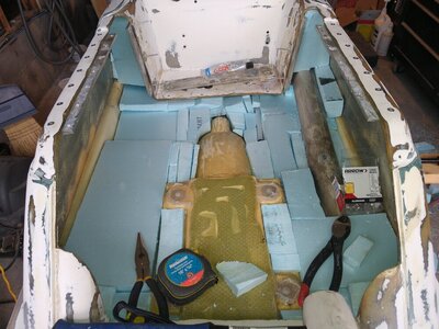
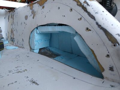
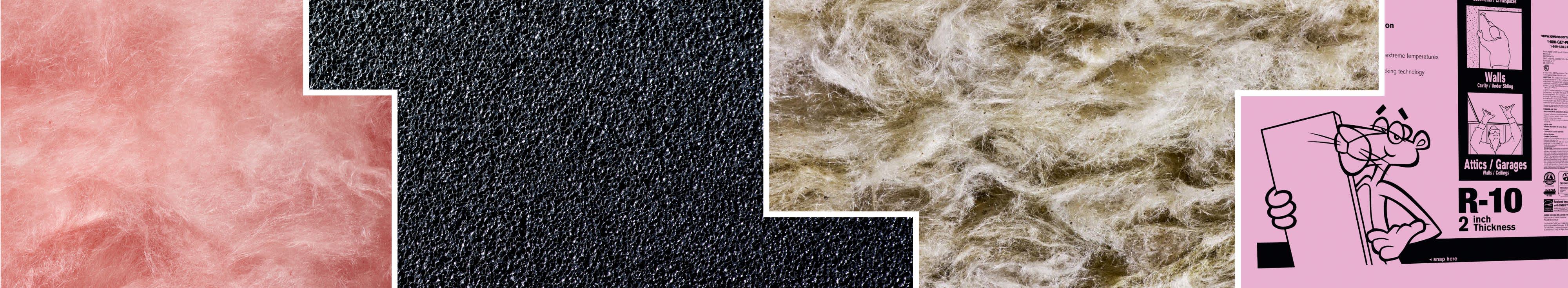
Initially, when researching the different manufacturers and where to get it, I learned that when it is in the form of 7 or 10 inch thickness, it is called dock billet. While this is not widely available for me in my location, what I have found is Dow Highload 100 blue rigid foam intended for use under load bearing surfaces such as airport runways etc. It is closed cell foam with the desired 100 psi compressive strength. It is also regarded as beneficial for use in marine applications where there is a need for structural integrity, and in the right thickness it can be used for artificial islands like docks, golf course islands and the like. The sheet size I bought comes as a 2" thick by 24" wide and 8' length. I will cut it accordingly and laminate it using Lepage PL300 foam board adhesive. This adhesive is specially formulated to bond well to foam and not attack it deteriorating it. I will update with photos later this week.

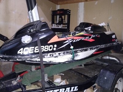
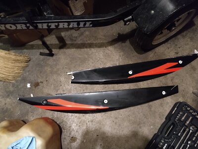
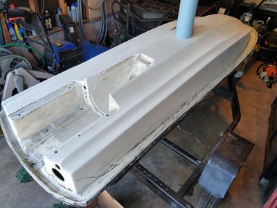
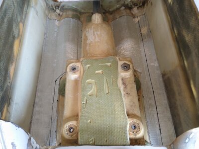
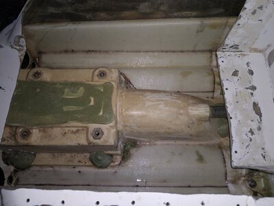
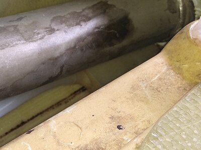
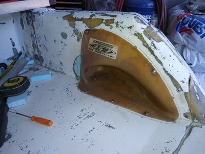
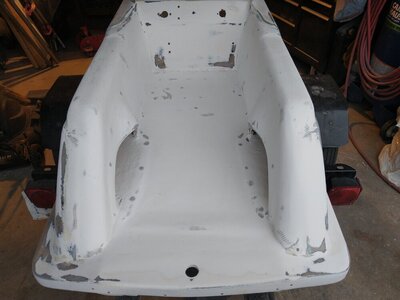
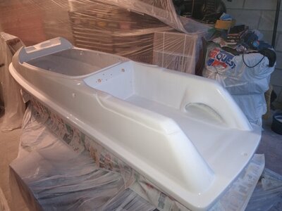
On a plus side, my original repair job using aluminum threaded backing plates worked to my benefit. I was able to chisel off the old glass repair work...with a good bit of difficulty mind you...and expose the fasteners for re-use on this next repair. I will also be removing the scupper system as I had sealed it off a long time ago due to constantly leaking one way valves and engine compartment flooding. I have gone this long without it, that proves I really do not need it. While I'm at it, I will be removing the Tom21 sponsons I installed years ago because the first 1/4 of the front portion on the left side eventually broke off. I will be turning my hull back into a mostly stock hull and keeping that way. Below are some links to some 100 psi capable foam options.


My Method For Aftermarket Carburetor Air Flow Synchronizing

I put together a quick run down of how I synchronize carbs. It is just a simple explanation of my methods that have given me the best results and worked reliably for me for many years now. So to get onto it...

When setting up aftermarket carbs for air flow the first things I do are to make sure all the hardware settings are the same. All mixing screws are setup to where I would normally start off to get the ski running relatively well, both throttle valves are adjusted to be closed at the same time without the idle screw holding the valves/butterflies open and the flame arrestors are off. Next I get my idle setup to about what I figure is proper, the tach bounces around a little bit so I just try to get a decent on trailer speed set up. When I'm happy with my initial idle speed I set my sync meter up, it gets friction fitted into the carb openings. For the bigger carbs like the Full Spectrum 48s, there is an adapter you can buy for this meter to suit those diameters. This one will go in and just barely fill the void but it's best to get the adapter for a proper seal. I want the full airflow going through the meter only.

With the hardware setup and ready, I check the airflow. The little orange pin will raise up indicating where you're at. The following photos are just to show what I do with a basic understanding of what I look for on a set of aftermarket carbs where the throttle shaft is a little more difficult to work with.

This section is for aftermarket carbs only that require a throttle shaft coupler system not typical to OEM carbs.

In the first photo, I have a description of the only parts I need to pay attention to when doing this. I call the carburetor with the throttle cable carb #1 because it does all the controlling, carb #2 just follows its lead. If I find that for example carb 2 isn't flowing the same amount of air, I shut the ski down and begin either loosening the second carb at the throttle shaft if I can, or I remove the cab setup just enough to get access to the set screws on the throttle shaft coupler. The speed plate is a really nice thing for doing these changes.

Photo 2 shows an example of where the meter typically runs at but not always, it will change with idle speed.
Photo 3 shows a possible scenario where carb 2 has a lower airflow.
Photo 4 - I only loosen the carb 2 side of the throttle shaft coupler as I will be increasing the airflow through that carb to balance with carb 1
Photo 5 - back the idle screw out until it is not putting any pressure on the idle speed set tab. I count how many turns out I go with it too so I can return to my predefined idle speed from before
Photo 6 - I insert a thin 0.002" shim between the valve and carb body as a starting point, this keeps the valve open ever so slightly to increase the airflow hopefully to match the volume being processed through carb 1
Photo 7 - with an eraser on a pencil, I compress the shim to take shape with the bore of the carb
Photo 8 - while holding the valve in place with the pencil I tighten up the throttle shaft set screws
Photo 9 - re-install the carb setup and test again with the flow meter, if the flow hasn't improved enough, I will move up incrementally with the shim thickness until I get as close as possible on a matched air flow
What I am doing here is compensating for any differences in hardware through the throttle valve position to get as equally balanced air flow as possible and it only takes a very very subtle change in that position to make it happen. When it is balanced, both carbs will be pulling the same volume of air through and then the fuel tuning can begin.
 

Attachments

  • Sync 01.jpg
    Sync 01.jpg
    137.6 KB · Views: 76
  • Sync 02.jpg
    Sync 02.jpg
    124.9 KB · Views: 69
  • Sync 03.jpg
    Sync 03.jpg
    128 KB · Views: 58
  • Sync 04.jpg
    Sync 04.jpg
    133.7 KB · Views: 55
  • Sync 05.jpg
    Sync 05.jpg
    106.3 KB · Views: 52
  • Sync 06.jpg
    Sync 06.jpg
    138.3 KB · Views: 49
  • Sync 07.jpg
    Sync 07.jpg
    153.7 KB · Views: 46
  • Sync 08.jpg
    Sync 08.jpg
    194 KB · Views: 47
  • Sync 09.jpg
    Sync 09.jpg
    138.3 KB · Views: 51
My Method For OEM SBN 38 and SBN 44 Carburetor Air flow Synchronizing

OEM carburetor synchronizing on a Yamaha 62t base is quite possibly the easiest thing a person can do. In the following photos you will see how I do it.

In photo one, I identify the carburetors the same as above, carb #1 has the throttle cable and is the controlling carb, carb #2 is just following its lead.
I make sure that both carbs have the same hardware settings such as both sets of mixing screws are at the same settings according to their circuits, and both throttle valves have been closed at the same time with no idle set screw pressure on the tab. There is a throttle valve sync screw in between the OEM cabs as seen in photo 4. There is actually 2 of these, one is for the chokes, the other for the throttle. I never use the chokes so I remove them and replace with a primer system.
Photo 2 - while the ski is running with a basic setup and generic idle speed setting that I am happy with I friction fit the air flow meter into the carb openings. On OEM 38 and 44 carbs, it will hold in there nice and snug.
Photo 3 - If I get an under performing reading as seen in photo three, I simply tighten down the sync screw very minimally while the motor is still running, remove the screwdriver and allow the motor to settle down. It will raise in idle speed a good bit because you have to put some pressure on the screwdriver to turn that screw. Once I get the flow meter to read the same as carb one that's it, syncing is done. I will double check both carbs after all adjustments too just to be sure both are flowing at equal amounts. So that's it, there's how I have been doing this for a long time now and always had very good results. Thanks for reading.
 

Attachments

  • Sync 10.jpg
    Sync 10.jpg
    159.4 KB · Views: 50
  • Sync 11.jpg
    Sync 11.jpg
    149.6 KB · Views: 46
  • Sync 12.jpg
    Sync 12.jpg
    141.4 KB · Views: 44
  • Sync 13.jpg
    Sync 13.jpg
    155.2 KB · Views: 48
Last edited:
My sync tool is this, there are Chinese versions that are terrible, I just stick with the German made one.

 
A little quick update, the set of aftermarket carbs shown in the above post, I just setup these up this evening for their first time since I have had access to them. I left my good set of shim gauges at home with all the shims down to 0.0005" and only had a 0.006" shim available. I gave it a try just because. I pretty well figured it was too much and sure enough it was, so I decided to look around for something else that would be a decent bit of shim and came up with a piece from an old carb kit as seen in the photo. I had to bring more air into carb 2 to match #1, so as mentioned above, I loosened the throttle shaft coupler screw on carb 2's side, slipped this thin plastic fuel pump diaphragm into the carb bore the same way as the shim gauge would go, I only used a corner of it though to keep it as close to the center of the bore as possible, held the throttle valve tight compressing the plastic, tightened everything back up and fired up the ski. It was exactly the thickness needed and synced the airflow to the same volume throughput of carb 1. Before doing this, the ski was running a little rough, after doing this it smoothed out a nicely and has a clean and consistent idle now. I just wanted to show this because even in a pinch, you can find a shim just about anywhere.
 

Attachments

  • IMG_20210907_191207639.jpg
    IMG_20210907_191207639.jpg
    117.2 KB · Views: 44
I'll be slowly updating this post now that things are somewhat settling down around here...for now. But on a quick update as to what has been going on, last year I breached my hull in the tray section. I firmly believe it was because the pool noodle idea although good for its buoyancy, no good for any strength...as we're all very aware lol. I had them jammed in there as tight as I could but there's only so much they can do. Because they're not really designed to be strong by any means, I believe my bottom deck buckled from all the harsh pounding causing the breach. It also extended into flex cracking a fair distance under the bond rail. Since I had to start getting rid of paint in preparation for repair work I decided I will go back to a much more visible color on the water and will be returning to the original white but with a new decal package. So the paint removing process begins. In addition, one of my Tom21 sponsons snapped off about the leading 4 inches even with them being screwed, bolted and 3M 5200 glued in place.
 

Attachments

  • IMG_20210405_193715995.jpg
    IMG_20210405_193715995.jpg
    91.2 KB · Views: 34
  • IMG_20210309_190542348.jpg
    IMG_20210309_190542348.jpg
    157 KB · Views: 34
  • IMG_20210424_162210099.jpg
    IMG_20210424_162210099.jpg
    172 KB · Views: 35
  • Sponsons.jpg
    Sponsons.jpg
    138.8 KB · Views: 18
Last edited:
Time for some updates, after being put through quite possibly the worst year of my life I still tried to muster up some desire to get out there and work on my ski. Now that the most labor intensive part is over, I can start updating here again. After much time and effort, I finally cleaned off all the black paint. Between the mouse sander and the paint remover, and far too many hours, the hull has been completely stripped of the black it once was. In the one photo you can see more thoroughly how bad the hull breach was.
 

Attachments

  • IMG_20210512_200205252_HDR.jpg
    IMG_20210512_200205252_HDR.jpg
    107.2 KB · Views: 23
  • IMG_20210517_202413726.jpg
    IMG_20210517_202413726.jpg
    128.8 KB · Views: 22
  • IMG_20210519_095327799_HDR.jpg
    IMG_20210519_095327799_HDR.jpg
    145.9 KB · Views: 21
  • IMG_20210529_193820085.jpg
    IMG_20210529_193820085.jpg
    196.7 KB · Views: 23
With the hull propped up on its side it was time to start laying up the new 0/90 biaxial stitch fiberglass. I decided to redo the reinforcement in the engine bay as well as the tray area for a fresh start and address any questionable areas from my first time ever doing it. For the resin I used a product called East System epoxy resin. It's the same product from my first go at this and much like West System but much more readily available here in southeastern Ontario Canada. For mixing the resin I bought a set of calibrated pumps, one pump of each gives the proper mix ratio, then I mixed it with a paint stir stick in a small roll tray. For applying it on the initial round, I just poured it onto the glass and worked it in with a small foam roller. This let me really press the resin in and work the air bubbles out. On the places that needed more attention like the bond rail and in between the hull and motor mount risers, I used the end of the stir stick and a small 2 inch paint brush. The generic supplies like the brushes and trays I picked up from Walmart since they're expendable and the quality of them won't matter anyway. But to my surprise the trays were really quite good for being around $2 each.
 

Attachments

  • IMG_20210619_173815466.jpg
    IMG_20210619_173815466.jpg
    136.2 KB · Views: 23
  • IMG_20210619_183256382.jpg
    IMG_20210619_183256382.jpg
    97.9 KB · Views: 23
  • IMG_20210619_191649525.jpg
    IMG_20210619_191649525.jpg
    172.3 KB · Views: 22
  • IMG_20210620_110700190.jpg
    IMG_20210620_110700190.jpg
    153.6 KB · Views: 21
  • IMG_20210620_110721579.jpg
    IMG_20210620_110721579.jpg
    93.5 KB · Views: 20
  • IMG_20210620_122900575.jpg
    IMG_20210620_122900575.jpg
    105.8 KB · Views: 21
With the sides all done it was time to address the floor as I had noticed some spider cracking developing.
 

Attachments

  • IMG_20210621_193130231.jpg
    IMG_20210621_193130231.jpg
    149.4 KB · Views: 21
  • IMG_20210621_195114938.jpg
    IMG_20210621_195114938.jpg
    162.9 KB · Views: 23
  • IMG_20210621_213127250.jpg
    IMG_20210621_213127250.jpg
    108.8 KB · Views: 25
I laid up some sections of glass to the best I could manage and epoxied it in. I covered all areas of the tray walls and covered over my old scupper and exhaust holes. I stopped using the scrupper years ago when they kept failing and leaking. Unbeknownst to me the thread in plugs had began leaking and the tube was full of water when I removed it. Once the glass had set up fully it was time to fair in the covered holes and bring back the hull to it's original look. I did this same thing on the side where the breach was as well as filled in the holes from where the sponsons were bolted through. I used a product called Pettit EZ Tex marine epoxy. It's a 1:1 mix just like JB Weld, you match equal scooped out portions and stir to blend. A fully mixed batch is white and when fully cured has a nice glossy white finish. It's sandable and paintable and seems to be quite strong. This will be a handy product for later when I finish the tray. While letting the epoxy filler cure I took some time to use some Marine Goop and made the top of the pump mount holes a sealed area too. I don't want water finding a way in if I can help it. I threaded in the pump bolts according to how far in they normally would go with the pump installed, then I went about 3/16" deeper just in case they went further than I expected, made a form around the bronze nuts with painters tape and filled it up with the Marine Goop at a height just below the surface of the tray when in place. The result was a real nice gummy sealing my tray from the pump bolts. While I was in there I also put all new steering cable tube hardware and seals in. I knew my steering cable tube was leaking heavily so it was time to seal up everything to the best I could. I'm hoping this will be the last time I ever have to go into the tray. I also faired in the original holes Yamaha used for the expanding foam filling. Originally they just put round white stickers over the holes. The old scupper tube hole in the engine compartment was given a refill too.
 

Attachments

  • IMG_20210621_190202009.jpg
    IMG_20210621_190202009.jpg
    145.4 KB · Views: 24
  • IMG_20210621_213149229.jpg
    IMG_20210621_213149229.jpg
    123.3 KB · Views: 25
  • IMG_20210624_170519953.jpg
    IMG_20210624_170519953.jpg
    125 KB · Views: 26
  • IMG_20210711_180056552_HDR.jpg
    IMG_20210711_180056552_HDR.jpg
    134.6 KB · Views: 26
  • IMG_20210711_183612429.jpg
    IMG_20210711_183612429.jpg
    101.8 KB · Views: 25
  • IMG_20210722_155208824.jpg
    IMG_20210722_155208824.jpg
    95.2 KB · Views: 28
  • IMG_20210722_155218205.jpg
    IMG_20210722_155218205.jpg
    108.8 KB · Views: 27
  • IMG_20210723_154321407.jpg
    IMG_20210723_154321407.jpg
    123.6 KB · Views: 27
  • IMG_20210921_193045778.jpg
    IMG_20210921_193045778.jpg
    96.6 KB · Views: 30
Last edited:
I went ahead and trimmed the excess off the gummies and began figuring out what I was going to do for insurance should the tray begin to leak, how would I get the water out. The thought came to me to setup a pair of permanent siphon bilges. I went to the hardware store, in this situation it was a place called Rona, but Home Depot would have it too, and I bought 10 feet of 1/2" semi-transparent PVC tube. This fits snuggly over the siphon boxes and should last the life of the ski now. I used a peice of 1/2" stainless tube, added a PVC Y fitting to it and put it through the firewall where I used the Marine Goop to seal it in place. That Marine Goop is good stuff and in my view, quite underrated. I've had things stay unbelievably well bonded with that stuff for over a decade. When I finally decided to take it apart it was a real chore. It stayed bonded until I ended up cutting it off.

Now that all the plumbing is back in place and Marine Gooped in, the last part was the worst part... getting the specialty high density foam cut and fit into place. This was the most time consuming thing of this whole project. For this I had to work around several variables. The tubes couldn't be crushed or bent, the pump tunnel has varying angles and the tray depth needs to be properly filled. But also the sides need some structure to help prevent any stressed from hard landings so they don't try to collapse as they did before causing the initial breach. The foam I used is called A100 Styrofoam. It cost $86 per sheet of 2 inches thick by 2 feet wide and 8 feet long. It has a compressive strength of 100 PSI, a water absorption rating of 0.1% which basically meanes it won't absorb water, and is used as a sublayer in construction settings for things like airport runways or as dock floatation. It was extremely tough to work with. I started out using a utility knife to cut it, that was far too much work and made the knofe go dull in half an hour. I tried a dual blade electric kitchen knife, the motor burnt out after 6 cuts, a hot wire foam cutter that would run out of steam because it stands up to heat surprisingly well. I eventually gave up with finesse and went big. It took a Ryobi reciprocating saw, regular sized hacksaw, and small fine work hacksaw to cut it accordingly. It was a real mess too, blue foam bits everywhere,
 

Attachments

  • IMG_20210824_181416303.jpg
    IMG_20210824_181416303.jpg
    123.2 KB · Views: 28
  • IMG_20210829_154743368.jpg
    IMG_20210829_154743368.jpg
    113.7 KB · Views: 27
  • IMG_20210829_150740828.jpg
    IMG_20210829_150740828.jpg
    71.6 KB · Views: 26
  • IMG_20210829_151243348.jpg
    IMG_20210829_151243348.jpg
    80.3 KB · Views: 26
  • IMG_20210829_151509001.jpg
    IMG_20210829_151509001.jpg
    139.1 KB · Views: 24
  • IMG_20210824_181355435.jpg
    IMG_20210824_181355435.jpg
    104.7 KB · Views: 24
  • IMG_20210829_153328178.jpg
    IMG_20210829_153328178.jpg
    115 KB · Views: 24
  • IMG_20210829_153400926.jpg
    IMG_20210829_153400926.jpg
    125.1 KB · Views: 23
  • IMG_20210829_162443576.jpg
    IMG_20210829_162443576.jpg
    109.2 KB · Views: 23
  • IMG_20210829_155648221.jpg
    IMG_20210829_155648221.jpg
    119.7 KB · Views: 26
Last edited:
After a lot of fitting up small pieces, the tray is as full as I can get it. Most had to be persuaded to fit in using a rubber mallet as you can see by the dent marks on top but the PVC hoses are free and not being kinked or crushed, the aluminum tubes are free as well, now for the tray top. I had some aluminum flat bars in there from my first attempt at doing tray work when I removed the wet foam. I re-used those bars this time but went with rivets instead. It was much easier to work with and seems to be plenty strong for the purpose they need to serve. The weight handling will now be all on the top of the pump tunnel and high strength foam, there shouldn't be any real load put against the rivets beyond what they can handle. The rivets also have aluminum washers fit for them as additional strength backers. The next time consuming ordeal was again the foam and getting custom fit pieces up the gunwhales inside. I tried to keep as much fill as I could while maintaining a tight fit for structure. I would rivet only a couple of holes at a time, fill in the area using the prybar to pull the tray platform out for extra working room, fill some more and rivet a couple of holes again. Eventually everything worked out and the tray is complete. Time to secure in the footholds. I used to have a set of Eric Mallone footholds but found the finish on them is not very good. The bottom flat areas for screwing down to the tray had waves in them leaving lifted areas that you could only glass over. I wasn't a fan of them. I also found they're quite overly spacious even with turf and underpad. As the turf and underpad begin to compress, the holds become very loose feeling. I've slipped out of these holds quite a few times. Fortunately I had a set of 24/7 holds I bought years ago with the intention of installing into my old 650sx. I'm glad I never got around to that project. I really like the fit and feel of these much more than the EME set, so these are the ones now installed. To really give strength to the tray, this time I put down two full layers and went full depth into the footholds. This will help disperse the weight load across the glass more evenly. The last time I did this I had the glass overlapping the outer edge of the holds by only a couple of inches. It did take its toll on them. I noticed the one hold began to crack.
 

Attachments

  • IMG_20210831_170818690.jpg
    IMG_20210831_170818690.jpg
    126 KB · Views: 24
  • IMG_20210831_170829628.jpg
    IMG_20210831_170829628.jpg
    134.6 KB · Views: 24
  • IMG_20210902_175400351.jpg
    IMG_20210902_175400351.jpg
    147.3 KB · Views: 25
  • IMG_20210913_213115259.jpg
    IMG_20210913_213115259.jpg
    142 KB · Views: 25
  • IMG_20210918_165240833.jpg
    IMG_20210918_165240833.jpg
    95.8 KB · Views: 26
  • IMG_20210919_135111882.jpg
    IMG_20210919_135111882.jpg
    105.8 KB · Views: 27
  • IMG_20210918_170013550.jpg
    IMG_20210918_170013550.jpg
    133.9 KB · Views: 26
  • IMG_20210919_181359264.jpg
    IMG_20210919_181359264.jpg
    136.9 KB · Views: 26
  • IMG_20210919_165749515.jpg
    IMG_20210919_165749515.jpg
    142.5 KB · Views: 25
  • IMG_20210920_185047366.jpg
    IMG_20210920_185047366.jpg
    171.8 KB · Views: 25
After applying the second layer of glass and letting it cure it was time to put the marine epoxy to work. I wanted to most strength I could get with the supplies I had because getting more right now takes up to 6 weeks at a time. This also gave the tray an almost OEM appearance, almost like it was made into the top deck mould.
 

Attachments

  • IMG_20210920_185054953.jpg
    IMG_20210920_185054953.jpg
    200.1 KB · Views: 24
  • IMG_20210920_185117102.jpg
    IMG_20210920_185117102.jpg
    168.4 KB · Views: 25
  • IMG_20210920_195847193.jpg
    IMG_20210920_195847193.jpg
    116.4 KB · Views: 24
  • IMG_20210921_190200822.jpg
    IMG_20210921_190200822.jpg
    135.9 KB · Views: 25
  • IMG_20210921_190207738.jpg
    IMG_20210921_190207738.jpg
    134.8 KB · Views: 24
  • IMG_20210921_200521845.jpg
    IMG_20210921_200521845.jpg
    124.5 KB · Views: 24
  • IMG_20210921_215318779.jpg
    IMG_20210921_215318779.jpg
    97.8 KB · Views: 24
  • IMG_20210922_181101338.jpg
    IMG_20210922_181101338.jpg
    89.7 KB · Views: 24
Finally onto some painting, this has never been my strong spot. I'm a better mechanic than I am a painter. For the most part though it has been turning out alright. I'm still working on the top deck because I have to wait for the right temperature days, we don't have many more heat days so it's taking me a lot longer than I care to. This is where I am at for now. It needs one more clean up and recoat, then I can begin to install the hardware...engine, steering etc. and finally will come new graphics kit.
 

Attachments

  • IMG_20210726_125804894.jpg
    IMG_20210726_125804894.jpg
    103.4 KB · Views: 25
  • IMG_20210726_135734923_HDR.jpg
    IMG_20210726_135734923_HDR.jpg
    106.4 KB · Views: 26
  • IMG_20210726_183837887_HDR.jpg
    IMG_20210726_183837887_HDR.jpg
    211.2 KB · Views: 27
  • IMG_20210806_164440431.jpg
    IMG_20210806_164440431.jpg
    103.7 KB · Views: 26
  • IMG_20210806_164506834.jpg
    IMG_20210806_164506834.jpg
    99.4 KB · Views: 24
  • IMG_20211015_182449061.jpg
    IMG_20211015_182449061.jpg
    99.4 KB · Views: 24
  • IMG_20211015_182505818.jpg
    IMG_20211015_182505818.jpg
    100.6 KB · Views: 24
  • IMG_20211015_182529662.jpg
    IMG_20211015_182529662.jpg
    83.8 KB · Views: 23
  • IMG_20210824_190007491.jpg
    IMG_20210824_190007491.jpg
    84.8 KB · Views: 29
Top Bottom