Liquid Graffix
liquidgraffix
- Location
- In the shop or on the water
I couldn’t find a full thread on a motor build up so… as I recently built a motor for someone, I decided to create a build thread to assist anyone else who decides to build/rebuild their own motor.
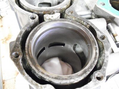
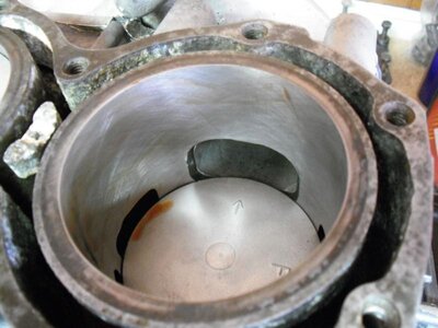
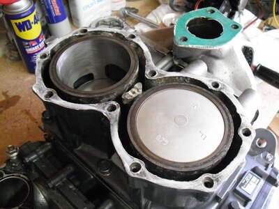
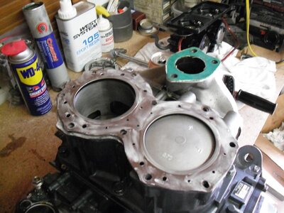
The motor that I built here was a 701-62T cases with a 61X cylinder. It had the intake manifold and carbs already on it. Also, the exhaust manifold was already bolted to the cylinder. Not a big deal, but if it weren’t on there then it would have been a bit easier.
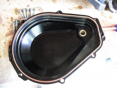
First of all, you want to make sure that all of the parts are accounted for! Nothing worse than getting into it and finding out that you are missing bolts. I lay everything out by the section I am working on.
Below is a list of the bolt sizes and the torques specs for each bolt. Notice that there are two specs for each. Torque each bolt to the first spec the first time through, and then come back and torque to the next spec as a final pass.
BOLT: SOCKET SIZE: 1st torque Final torque (ft-lb)
Case Bolts 12mm 11 20
Bed Plate 14mm 17 34
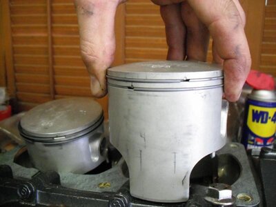
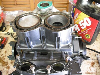
Cylinder 14mm 17 29
Head 12mm 11 26
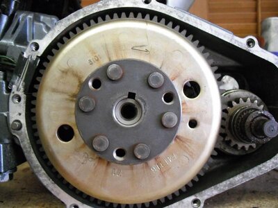
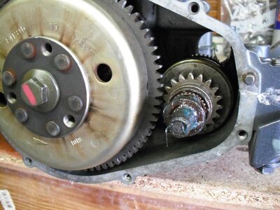
Flywheel 17mm -- 51
Once you have all of the parts and they are clean and ready to go:
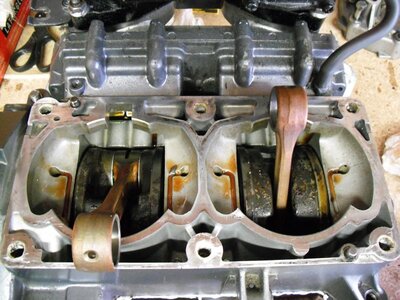
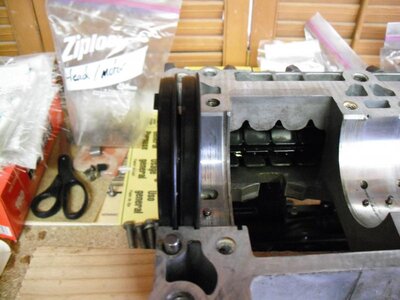
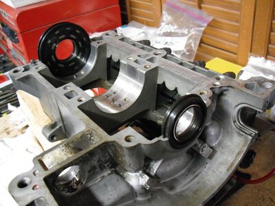
1. Begin by flipping the TOP half of the cases over so the pins are showing. (The bearings of the crankshaft will fit into them when it is installed in the cases) It is best to use blocks of wood or something similar to elevate the case half to allow for the rod to hang through.
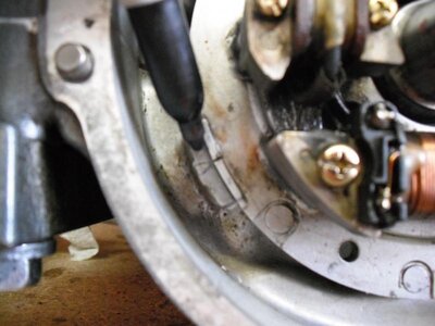
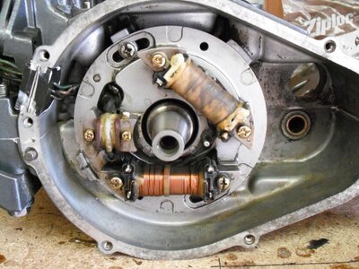
***The crank seals must be installed a certain way. (see pics)
(I test fit everything before I final assemble it)
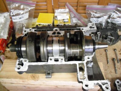
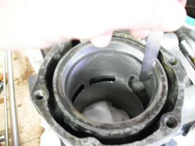
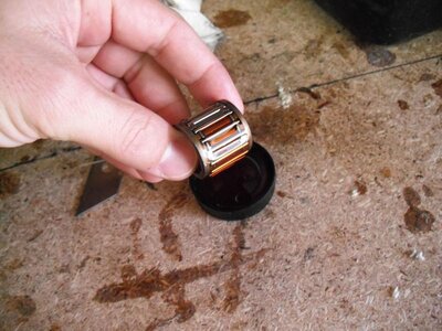
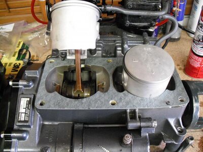
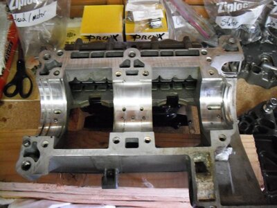
2. Install seals onto the crankshaft and lay it in the cases. Be Sure to apply a thin layer of grease to the seals where they slide onto the crank. Make sure that ALL of the bearings line up with the pins in the cases. Use your hand to try to turn each bearing to make sure it is secure. Now that the crank is half way in, I like to put oil in each bearing before sealing up the cases. Just pour some R50 down between each bearing.
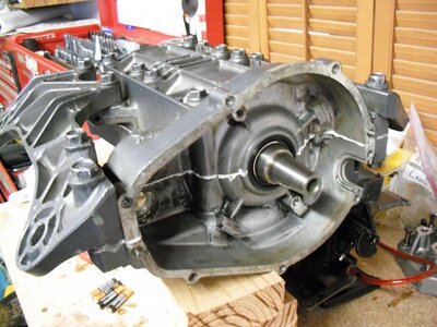
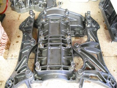
3. Apply a thin layer of 1211 to the surface of the case halves to seal them when tightened down. Line up the BOTTOM half of the case BEFORE pushing it down flush. Double check to see that the oil seals are lined up with the right groove in the case half. Once they are lined up, press the cases together. There are 8 bolts that hold the cases together and another 7 that hold the mounting plates on. (The tightening order is listed on the bottom half of the case)
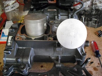
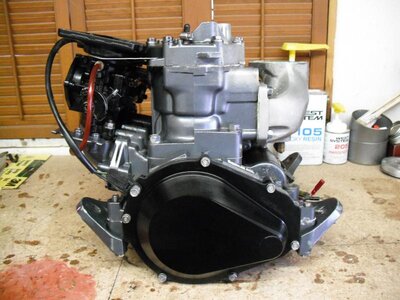
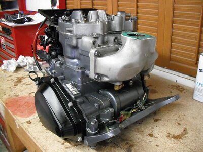
Once everything is tight, you can flip the bottom end over and begin assembly on the top portion of the motor. This is also a good time to apply some oil to the bottom rod bearings while they are accessible
The motor that I built here was a 701-62T cases with a 61X cylinder. It had the intake manifold and carbs already on it. Also, the exhaust manifold was already bolted to the cylinder. Not a big deal, but if it weren’t on there then it would have been a bit easier.
First of all, you want to make sure that all of the parts are accounted for! Nothing worse than getting into it and finding out that you are missing bolts. I lay everything out by the section I am working on.
Below is a list of the bolt sizes and the torques specs for each bolt. Notice that there are two specs for each. Torque each bolt to the first spec the first time through, and then come back and torque to the next spec as a final pass.
BOLT: SOCKET SIZE: 1st torque Final torque (ft-lb)
Case Bolts 12mm 11 20
Bed Plate 14mm 17 34
Cylinder 14mm 17 29
Head 12mm 11 26
Flywheel 17mm -- 51
Once you have all of the parts and they are clean and ready to go:
1. Begin by flipping the TOP half of the cases over so the pins are showing. (The bearings of the crankshaft will fit into them when it is installed in the cases) It is best to use blocks of wood or something similar to elevate the case half to allow for the rod to hang through.
***The crank seals must be installed a certain way. (see pics)
(I test fit everything before I final assemble it)
2. Install seals onto the crankshaft and lay it in the cases. Be Sure to apply a thin layer of grease to the seals where they slide onto the crank. Make sure that ALL of the bearings line up with the pins in the cases. Use your hand to try to turn each bearing to make sure it is secure. Now that the crank is half way in, I like to put oil in each bearing before sealing up the cases. Just pour some R50 down between each bearing.
3. Apply a thin layer of 1211 to the surface of the case halves to seal them when tightened down. Line up the BOTTOM half of the case BEFORE pushing it down flush. Double check to see that the oil seals are lined up with the right groove in the case half. Once they are lined up, press the cases together. There are 8 bolts that hold the cases together and another 7 that hold the mounting plates on. (The tightening order is listed on the bottom half of the case)
Once everything is tight, you can flip the bottom end over and begin assembly on the top portion of the motor. This is also a good time to apply some oil to the bottom rod bearings while they are accessible
Attachments

Last edited by a moderator: